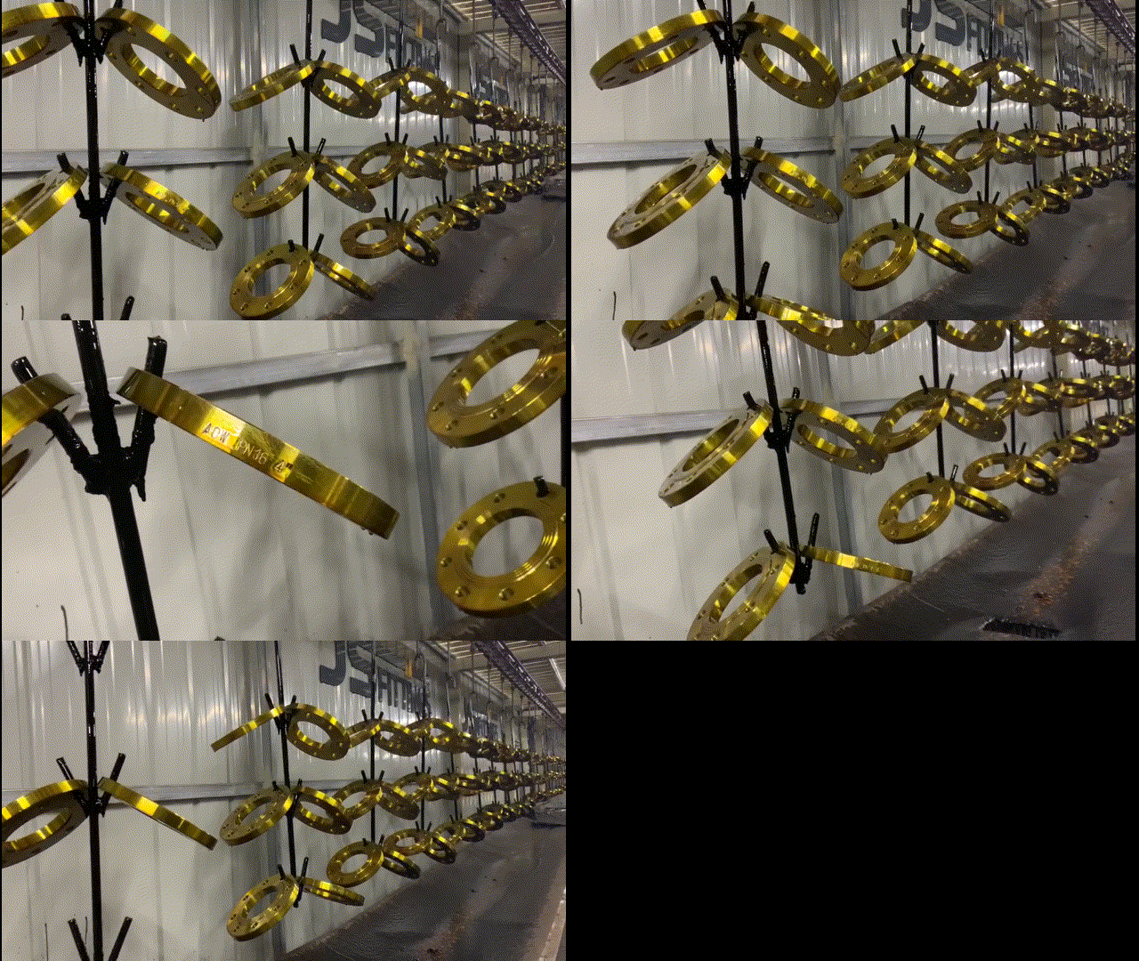
What is the flange?
Flanges are used when the piping joint needs dismantling. Flanges are used mainly for connecting pipes, valves, pumps, equipment, and specialties to form a piping system. They also provide easy access for cleaning, inspection, or modification. Flanges are usually welded or screwed with the pipe, valve, pumps, and equipment. A flanged joint is composed of three separate and independent although interrelated components: the flanges, the gaskets, and the bolts. Flanged joints are made by bolting together two flanges with a gasket between them to provide a seal.
Special controls are required in the selection and application of all these elements to attain a leak-proof joint.
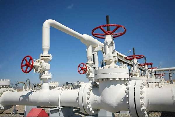
ASME B16.5 Pipe Flanges and Flanged Fittings: NPS 1/2 through NPS 24 Metric/Inch Standard covers pressure-temperature ratings, materials, dimensions, tolerances, marking, testing, and methods of designating openings for pipe flanges and flanged fittings.
Included are:
(1) flanges with rating class designations 150, 300, 400, 600, 900, and 1500 in sizes NPS 1/2 through NPS 24 and flanges with rating class designation 2500 in sizes NPS 1/2 through NPS 12, with requirements given in both metric and U.S. Customary units with a diameter of bolts and flange bolt holes expressed in inch units;
(2) flanged fittings with rating class designation 150 and 300 in sizes NPS 1/2 through NPS 24, with requirements given in both metric and U.S. Customary units with a diameter of bolts and flange bolt holes expressed in inch units;
(3) flanged fittings with rating class designation 400, 600, 900, and 1500 in sizes NPS 1/2 through NPS 24 and flanged fittings with rating class designation 2500 in sizes NPS 1/2 through NPS 12 that are acknowledged in Non-Mandatory Appendix E in which only U.S. Customary units are provided.
B16.5 is limited to flanges and flanged fittings made from cast or forged materials, and blind flanges, and certain reducing flanges made from cast, forged, or plate materials. Also included in this Standard are requirements and recommendations regarding flange bolting, flange gaskets, and flange joints.
This Standard is to be used in conjunction with equipment described in other volumes of the ASME B16 Series of Standards as well as with other ASME standards, such as the Boiler and Pressure Vessel Code and the B31 Piping Codes.
Materials for Flanges
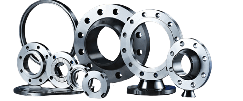
Pipe flanges are manufactured in all the different materials like stainless steel, cast iron, aluminum, brass, bronze, plastic, etc. but the most used material is forged carbon steel and has machined surfaces. JS FITTINGS has been producing carbon steel flanges for 37 years, with rich experience in manufacturing and exporting. ASTM A105, steel20, Q235 is carbon steel for high-temperature, ASTM A350 LF1, LF2, LF3 are carbon steel for low temperature. Alloy steel and stainless steel flanges are also available.
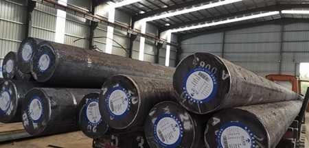
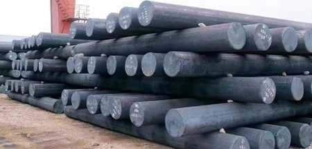
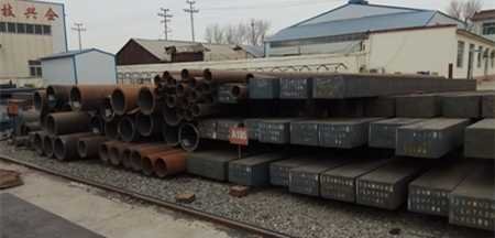
Material required for flanges and flanged fittings commonly are:
ASTM A105 for forged carbon steel flange
ASTM A350 for forged carbon steel, low alloy steel flange
ASTM A182 for alloy steel flange and stainless steel flange
ASTM A216 for casting carbon steel flanges
ASTM A352, ASTM A217
ASTM A515 Gr 70, 65 for plates flange
ASTM A516 Gr 70, 65 for carbon and low alloy steel plates flange
ASTM A203, A204
ASTM A387 Gr 11, 22, 91 CL 2 for alloy steel plates flange
ASTM A240 Grade 304/L, 316/L for stainless steel plate flange
Notes:
(1) Plate and flat bar materials shall be used only for blind flanges and reducing flanges without hubs.
(2) Flanges and flanged fittings shall be manufactured as one piece in accordance with the applicable material specification. Assembly of multiple pieces into the finished product by welding or other means is not permitted by this Standard
In addition, flanges, like fittings and pipes, for specific purposes sometimes internally equipped with layers of materials of completely different quality as the flanges themselves, which are “lined flanges”.
The material of a flange is basically set during the choice of the pipe, in most cases, a flange is of the same material as the pipe.
All flanges, discussed on this page fall under the ASME en ASTM standards unless otherwise indicated. ASME B16.5 describes dimensions, dimensional tolerances, etc., and ASTM the different material qualities.
Types of ASME B16.5 Flanges
There are most used flange types ASME B16.5 are Welding Neck Flange (or WN Flange), Slip On Flange (or SO Flange), Socket Weld Flange (or SW Flange ), Lap Joint Flange (or LJ Flange), Threaded Flange, and Blind Flange. Below you will find a short description and definition of each type, complete with a detailed image.
Weld Neck Flange - WN Flange
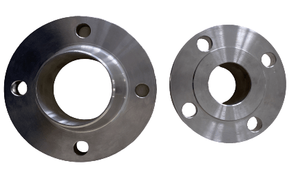
A welding neck flange also called the “WN” flange, features a long tapered hub that can be welded with a pipe.
This flange type is used, normally, in high-pressure and high/low temperatures applications that require an unrestricted flow of the fluid conveyed by the piping system, the bore of the flange matches with the bore of the pipe.
The absence of pressure drops prevents negative effects as turbulence and erosion/corrosion of the metals in the proximity of the flanged joints.
The tapered hub allows a smooth distribution of the mechanical stress between the pipe and the weld neck flange and facilitates the execution of radiographic inspections to detect possible leakages and welding defects.
The dimension of the flange (NPS and the pipe schedule) shall match the dimension of the connecting pipe.
A welding neck flange is connected to a pipe by a single full penetration V-shaped butt weld. you can contact us to get the dimension and weights of weld neck flanges in different standards.
Slip-On Flange - SO Flange
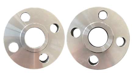
A slip-on flange is connected to the pipe or the fittings by two fillet welds, one executed inside and one outside the cavity of the flange.
The bore size of a slip-on flange is larger than the outside diameter of the connecting pipe, as the pipe has to slide inside the flange to be connected by the execution of a fillet weld.
Slip-on flanges are also defined as “Hubbed Flanges” and they are easy to recognize due to their slim and compact shape.
You can contact us to get the dimension of a slip-on flange or download directly.
Socket Weld Flange - SW Flange
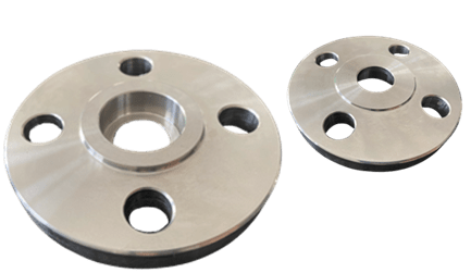
Socket Weld flanges were initially developed for use on small-size high-pressure piping. Their static strength is equal to Slip-On flanges, but their fatigue strength 50% greater than double-welded Slip-On flanges.
Socket weld flanges are connected to pipes using a single fillet weld executed on the outer side of the flange (different from the slip-on flange type that requires two welds).
According to ASME B31.1, to execute a flanged connection using a socket weld flange, the pipe shall be at first inserted in the socket of the flange until it reaches the bottom of the flange, then it should be lifted by 1.6 mm and finally welded.
This gap shall be left to allow proper positioning of the pipe inside the flange socket after the solidification of the weld.
Socket Weld Flanges are used for small-size and high-pressure piping that does not transfer highly corrosive fluids.
This due to the fact that these flange types are subject to corrosion in the gap area between the end of the pipe and the shoulder of the socket.
Their static strength of socket weld flanges is similar to slip-on flanges’, but their fatigue strength is higher due to the presence of a single, instead of double, fillet weld.
Lap Joint Flange - LJF
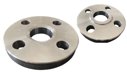
Lap Joint Flanges have all the same common dimensions as any other flange named on this page however it does not have a raised face, they used in conjunction with a “Lap Joint Stub End”.
These flanges are nearly identical to a Slip-On flange with the exception of a radius at the intersection of the flange face and the bore to accommodate the flanged portion of the Stub End.
Their pressure-holding ability is little, if any, better than that of Slip-On flanges, and the fatigue life for the assembly is only one-tenth that of Welding Neck flanges.
They may be used at all pressures and are available in a full-size range. These flanges slip over the pipe and are not welded or otherwise fastened to it. Bolting pressure is transmitted to the gasket by the pressure of the flange against the back of the pipe lap (Stub End).
Lap Joint flanges have certain special advantages:
Freedom to swivel around the pipe facilitates the lining up of opposing flange bolt holes.
Lack of contact with the fluid in the pipe often permits the use of inexpensive carbon steel flanges with a corrosion-resistant pipe.
In systems that erode or corrode quickly, the flanges may be salvaged for re-use.
Threaded Flange - Screwed Flange
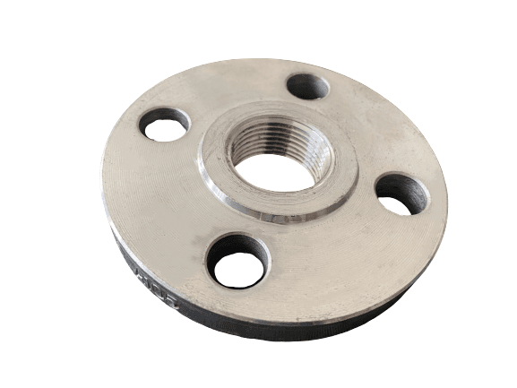
Threaded flanges are joined to pipes by screwing the pipe onto the flange without seam welds, Sometimes a seal weld is also used in conjunction with the threaded connection.
The pipe has a male thread, generally NPT per ASME B1.20.1. A threaded flange or fitting is not suitable for a pipe system with thin wall thickness, because the cutting thread on a pipe is not possible.
Threaded flanges are available in sizes up to 4 inches and multiple pressure ratings.
However, they are used, mostly, small size piping in low pressure and low-temperature applications, like water and air utility services.
Threaded flanges are also a mandatory requirement in explosive areas, such as gas stations and plants, as the execution of welded connections in such environments would be dangerous.
ASME B31.3 Piping Guide says:
Where steel pipe is threaded and used for steam service above 250 psi or for water service above 100 psi with water temperatures above 220° F, the pipe shall be seamless and have a thickness at least equal to schedule 80 of ASME B36.10.
Blind Flange
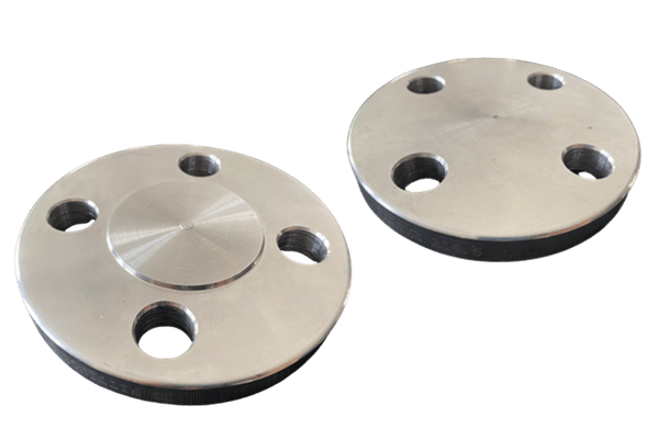
Contrary to all the flange types seen above, blind flanges do not have a center hole, and are used to blind or seal a pipeline, a valve/pressure vessel and block the flow of the fluid.
Blind flanges have to withstand remarkable mechanical stress due to the system pressure and the required bolting forces.
Blind flanges allow easy access to the pipeline, as they can be easily unbolted to let the operator execute activities inside the terminal end of the pipe (this is also the reason why the blind flange type is used as a manhole for pressure vessels, at times).
It is maybe interesting to observe that, while this flanges type is easier to manufacture, they are sold at a premium average cost per kilogram compared to the other flange types.
There are also other flange types that we can supply, such as plate flange, spectacle flange, orifice flange, and so on.
Dimensions of ASME B16.5 Pipe Flange
About the specification, ASME B16.5 covers the dimensions of steel flanges up to 24 inches; ASME B16.47 covers flanges above 24 inches; API 6A/6Bcover flanges for upstream oil and gas, EN 1092-1 covers European standard flanges.GOST 33259, GOST 12820, GOST12821covers Russian standard flanges.
ASME B16.5 flange dimensions including different pressure ratings for weld neck flange, slip on flange, blind flange, reducing flange, socket weld flange, threaded flange, view below for more details.
Weld Neck RF Flange and Its Sealing Face Types for ASME B16.5 Standards
Raised Face Flange - RF
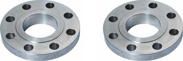
The Weld Neck RF Flange is the most common type used in process plant applications and is easy to identify. It is referred to as a raised face because the gasket surfaces are raised above the bolting circle face. This face type allows the use of a wide combination of gasket designs, including flat ring sheet types and metallic composites such as spiral wound and double jacketed types. The purpose of an RF flange is to concentrate more pressure on a smaller gasket area and thereby increase the pressure containment capability of the joint. For 150# and 300# flanges, the raised face is 1.6 mm (1/16 inch) and is included in the thickness specified. For a higher ratings, the flange thickness does not include the raised face thickness. The raised face thickness for a higher rating is 6.4 mm (1/4 inch). The typical flange face finish for ASME B16.5 RF flanges is 125 to 250 µin Ra (3 to 6 µm Ra).
Flat Face Flange - FF

The Flat-Face flange has a gasket surface in the same plane as the bolting circle face. Applications using flat face flanges are frequently those in which the mating flange or flanged fitting is made from a casting. Flat face flanges are never to be bolted to a raised face flange. ASME B31.1 says that when connecting flat face cast iron flanges to carbon steel flanges, the raised face on the carbon steel flange must be removed and that a full face gasket is required. This is to keep the thin, brittle cast iron flange from being sprung into the gap caused by the raised face of the carbon steel flange.
Ring Type Joint - RTJ

The Ring Type Joint Flanges are typically used in high pressure (Class 600 and higher rating) and/or high-temperature services above 800°F (427°C). They have grooves cut into their faces which seats ring gaskets. The flanges seal when tightened bolts compress the gasket between the flanges into the grooves, deforming the gasket to make intimate contact inside the grooves, creating a metal to metal seal. An RTJ flange may have a raised face with a ring groove machined into it. This raised face does not serve as a part of the sealing means. For RTJ flanges that seal with ring gaskets, the raised faces of the connected and tightened flanges may contact each other. In this case, the compressed gasket will not bear additional load beyond the bolt tension, vibration and movement cannot further crush the gasket and lessen the connecting tension.
Tongue and Groove Flange - TG

One flange face has a raised ring (Tongue) machined onto the flange face while the mating flange has a matching depression (Groove) machined into its face. The Tongue and Groove faces of these flanges must be matched. Tongue-and-groove facings are standardized in both large and small types. They differ from male-and-female in that the inside diameters of the tongue-and-groove do not extend into the flange base, thus retaining the gasket on its inner and outer diameter. These are commonly found on pump covers and Valve Bonnets. Tongue-and-groove joints also have an advantage in that they are self-aligning and act as a reservoir for the adhesive. The scarf joint keeps the axis of loading in line with the joint and does not require a major machining operation.
Male and Female Flange - MF
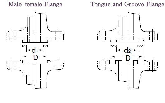
With this type, the flanges also must be matched. One flange face has an area that extends beyond the normal flange face (Male). The other flange or mating flange has a matching depression (Female) machined into its face. The female face is 3/16-inch deep, the male face is 1/4-inch high, and both are smooth finished. The outer diameter of the female face acts to locate and retain the gasket. Custom male and female facings are commonly found on the Heat Exchanger shell to channel and cover flanges. The female face and the male face are smooth finished. The outer diameter of the female face acts to locate and retain the gasket.
General flange faces such as the RTJ, T&G, and the F&M shall never be bolted together. The reason for this is that the contact surfaces do not match and no gasket has one type on one side and another type on the other side.
Face Finish of ASME B16.5 Pipe Flange
With this type, the flanges also must be matched. One flange face has an area that extends beyond the normal flange face (Male). The other flange or mating flange has a matching depression (Female) machined into its face. The female face is 3/16-inch deep, the male face is 1/4-inch high, and both are smooth finished. The outer diameter of the female face acts to locate and retain the gasket. Custom male and female facings are commonly found on the Heat Exchanger shell to channel and cover flanges. The female face and the male face are smooth finished. The outer diameter of the female face acts to locate and retain the gasket.
General flange faces such as the RTJ, T&G, and the F&M shall never be bolted together. The reason for this is that the contact surfaces do not match and no gasket has one type on one side and another type on the other side.
The most used surface
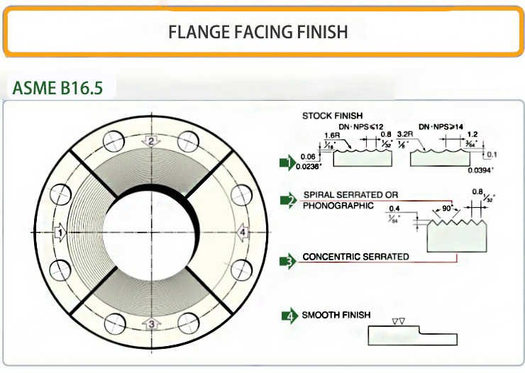
STOCK FINISH
The most widely used of any flange surface finish, because practically, is suitable for all ordinary service conditions. Under compression, the soft face from a gasket will embed into this finish, which helps create a seal, and a high level of friction is generated between the mating surfaces.
The finish for these flanges is generated by a 1.6 mm radius round-nosed tool at a feed rate of 0.8 mm per revolution up to 12 inches. For sizes 14 inches and larger, the finish is made with a 3.2 mm round-nosed tool at a feed of 1.2 mm per revolution.
SPIRAL SERRATED
This is also a continuous or phonographic spiral groove, but it differs from the stock finish in that the groove typically is generated using a 90-° tool which creates a “V” geometry with 45° angled serration.
CONCENTRIC SERRATED
As the name suggests, this finish is comprised of concentric grooves. A 90° tool is used and the serrations are spaced evenly across the face.
CONCENTRIC SERRATED
As the name suggests, this finish is comprised of concentric grooves. A 90° tool is used and the serrations are spaced evenly across the face.
SMOOTH FINISH
This finish shows no visually apparent tool markings. These finishes are typically utilized for gaskets with metal facings such as double jacketed, flat steel and corrugated metal. The smooth surfaces mate to create a seal and depend on the flatness of the opposing faces to effect a seal. This is typically achieved by having the gasket contact surface formed by a continuous (sometimes called phonographic) spiral groove generated by a 0.8 mm radius round-nosed tool at a feed rate of 0.3 mm per revolution with a depth of 0.05 mm. This will result in a roughness between Ra 3.2 and 6.3 micrometers (125 – 250 micro inch).
Tolerance of ASME B16.5 Pipe Flange
In order to determine compliance with this standard, where a fixed effective number is required where the limits, maximum and minimum values are specified, rounding shall be in accordance with the method defined in ASTM Practice E29.
Required tolerances for different flanges and flanged fittings elements are as follows:
Center to Contract Surfaces and Center to End Tolerances
(a). Center-to-Contract Surfaces other than Ring Joint
Size | Tolerance |
NPS ≤ 10 | +/- 1.0 mm (+/- 0.03 in.) |
NPS ≤ 12 | +/- 1.5 mm (+/- 0.06 in.) |
(b). Center-to-End (Ring Joint)
Size | Tolerance |
NPS ≤ 10 | +/- 1.0 mm (+/- 0.03 in.) |
NPS ≤ 12 | +/- 1.5 mm (+/- 0.06 in.) |
(c). Center surface-to-Contact surface other than ring joint
Size | Tolerance |
NPS ≤ 10 | ±2.0 mm(±0.06 in.) |
NPS ≥ 12 | ±3.0 mm(±0.12 in.) |
(d). End-to-End
Size | Tolerance |
NPS ≤ 10 | ±2.0 mm(±0.06 in.) |
NPS ≥ 12 | ±3.0 mm(±0.12 in.) |
Tolerances for Flange Facings
For both flange and flanged fittings facings tolerances are as follows:
(a) Inside and outside diameter of large and small tongue and groove and female, ±0.5 mm (±0.02 in.).
(b) Outside diameter,2.0 mm (0.06 in.) raised face, ±1.0 mm (±0.03 in.).
(c) Outside diameter, 7.0 mm (0.25 in.) raised face, ±0.5 mm (±0.02 in.).
(d) Ring joint groove tolerances are shown in Table 5 (Table II-5 of Mandatory Appendix II in ASME B16.5)
(e)Perpendicularity of the face with the bore as below table
Size | Tolerance |
NPS ≤ 5 | 1 deg |
NPS ≥ 6 | 0.5 deg |
Flange thickness tolerances
Size | Tolerance |
NPS ≤ 18 | +3.0, -0.0 mm (+0.12,-0.00 in.) |
NPS ≥ 20 | +5.0, -0.0 mm (+0.19,-0.00 in.) |
The plus tolerance is applicable to bolting bearing surfaces whether as-forged, as-cast, spot-faced, or back-faced.
Product Process of ASME B16.5 Pipe Flange
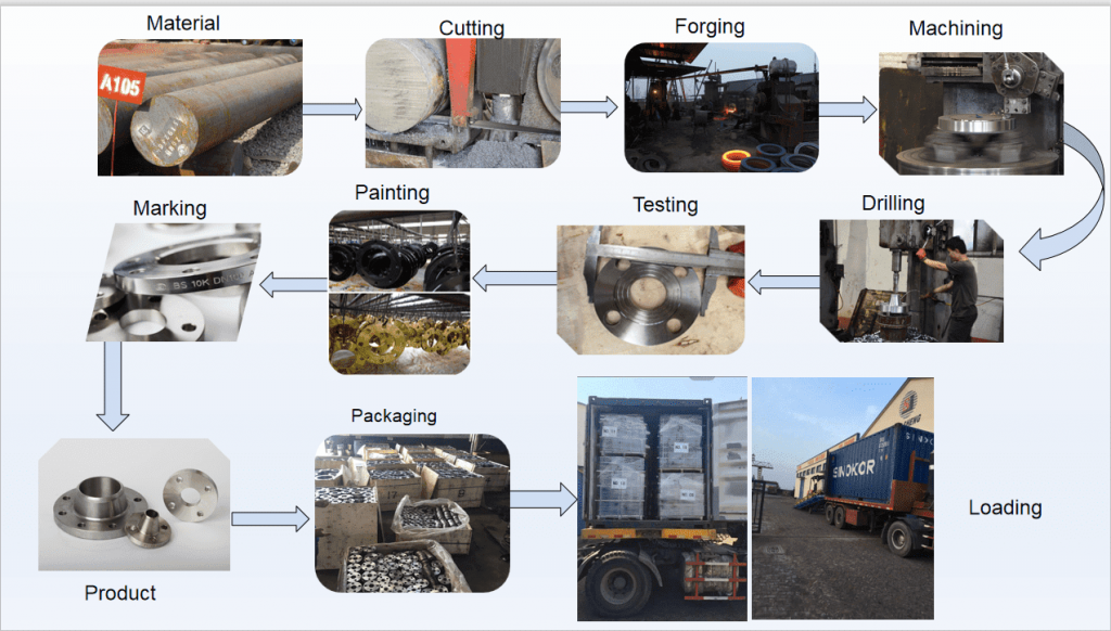
- Purchase material
According to the purchase contract, confirm the grade of the steel.
- Raw material inspection
2.1 Check the raw material MTC, including the standard, grade, chemical composition, heating No. Etc.
2.2 Analyze the chemical composition of the sample and check whether the composition shown is consistent with the MTC.
- Cutting
3.1 Count the weight of the material, the weight of the forging piece, net weight of the finished flange.
3.2 According to the counted data choose the material.
3.3 Cut the material bar
3.4 Mark the heat No. on the material piece
- Heat the material piece.
- Forge the workpiece, during the process, workers must check the temperature and forging rate.
- Heat treatment
According to material grade and effective heat dissipation size, choose the right heat treatment methods for the forging piece.
7.Rough machining to remove the oxide scale on the surface of the forging
- Build-up welding
- Ultrasonic Flaw Detection
- Smooth the surface
- Mark the flange
- Surface treatment, such as anti-rust oil coating, varnish painting, epoxy coating, etc…
- Inspect the size, surface, and mark.
Package the flanges and delivery to the customers
How to order flanges?
The following data shall be communicated to JS FITTINGS when ordering flanges:
The following data shall be communicated to JS FITTINGS when ordering flanges:
- Flange type (welding neck, slip-on, threaded, lap joint flange)
- Flange specification (example ASME B16.5, ASME B16.47 type A, EN 1092-1, JIS, UNI, DIN, etc.)
- Nominal pipe size (NPS)
- Flange rating (or class): flanges’ rating can range from 150 to 2500 for ASME flanges, from 5k to 30k for JIS B2220 flanges and KS1503 flanges; from PN 6 to PN 100 for European and Russian-standard flanges (DIN, UNI, EN 1092-1, GOST 12820 / 12821-80); Class 600/3, 1000/3, 1600/3, 2500/3, 4000/3 for SANS/SABS flanges (South African standard for flanges)
- Pipe schedule (for welding neck and socket weld flanges)
- Flange facing type (FF; RF, RTJ): according to ASME B16.5, the raised face is the standard facing for flanges (different facings, like RTJ or flat face FF, have to be ordered specifically)
- Flange surface finish (smooth, stock, concentric serrated, etc)
- Material grade (forged carbon, stainless, duplex, nickel-alloy steels or, non-ferrous materials as cupronickel, copper, aluminum, and bronze)
- Special package demands
- Quantity, the more the cheaper
